
See Figure 1 for face shell products of medical therapeutic instruments. Maximum dimensions of product are 198.00 mm * 156.00 mm * 48.00 mm; average thickness of plastic part is 2.00 mm, material of plastic part is ABS, shrinkage rate is 1.005, and weight of plastic part is 172.60 grams. Technical requirements for plastic parts are that there should be no defects such as peaking, underfilled injection molding, flow lines, pores, warping deformation, silver streaks, cold material, and jetting lines, and meet ROSH environmental protection requirements.

Figure 1 Product picture of face shell of medical treatment instrument
It can be seen from Figure 1 that basic shape of plastic part is a flat rectangular shell with a wide gap on one side and two round holes on this side. It is necessary to design core pull of front mold slider, and there are two small round holes on the other side parallel to it. Small round holes at these two places are symmetrical, and form hinge holes with other plastic parts during actual assembly. There is a sinking glue spot on the top surface of plastic part, which is battery compartment. There is no doubt that this structure must design a rectangular insert to facilitate mold processing and assembly. There are several deep and long bones on the back of plastic part, and there are many pillars next to it, which needs to be designed to eject cylinder. Long bones need to be designed with inserts to facilitate exhaust during processing and injection molding.
Size of plastic part is large, and front mold slider needs to be designed on the two sides, which needs to occupy a certain amount of space. Therefore, cavity design of mold is 1 cavity, mold base is standard mold base FCI-4040-A100-B90- For C120, reason for choosing to simplify fine runner mold base is to facilitate design of front mold slider and three-plate mold at the same time. Four corners of front and rear mold cores are respectively designed to locate positioning angle, which is convenient for accurate mold clamping. Under action of lateral force during injection molding, front and rear mold cores will not shift.
There are some skills in design of positioning angle. First, protrusion of positioning angle is selected on raised side of mold core, which can save steel, reduce amount of processing, and shorten processing time. More importantly, cavity of front mold is locked so that it will not be opened; angle of positioning angle design is generally 3゜~10゜. The smaller angle, the higher positioning accuracy and the higher accuracy of repeating compound mold, which is convenient to protect insertion position from being damaged; positioning angle needs to be precisely processed by CNC machine tools, and cannot be corrected by hand. Otherwise, Hukou loses its proper meaning. When positioning angle can be ground, it should be processed with a grinding machine as much as possible. When structure of mold core cannot be ground, use CNC machine tools to process it; when designing jaw, it is necessary to reasonably design gap between jaw and protrusion in the middle of mold core to facilitate passage of CNC milling cutter, especially when roughing, it is necessary to choose a larger diameter of knives. See Figure 4.
Three slider cores of front mold of plastic parts are all designed with bent pin driven front mold sliders. Shovel of front mold slider is fixed on panel. Since shovel is long and force of shovel is small, it is necessary to make an inclined backhoe on A plate, see 3D diagram.

Figure 2 3D drawing of mold
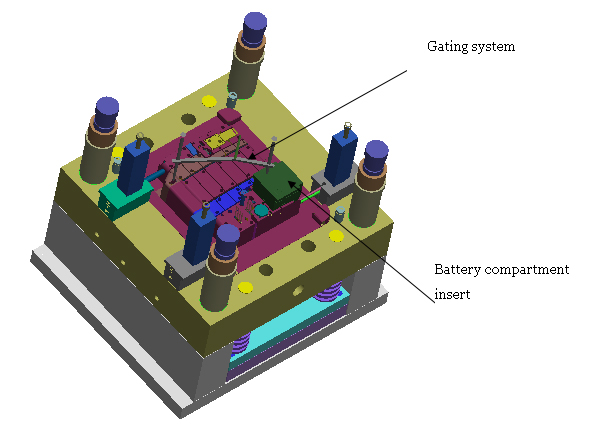
Figure 3 Die parting surface diagram
Size of plastic part is large, and flow of molten plastic is long. In order to ensure that the entire cavity can be filled quickly, a reasonable gating system needs to be designed. This set of molds is designed with two gates, one point gate is located in battery compartment, and the other is a latent gate located on the edge of plastic part, which is injected into mold cavity through thin nozzle to latent gate.

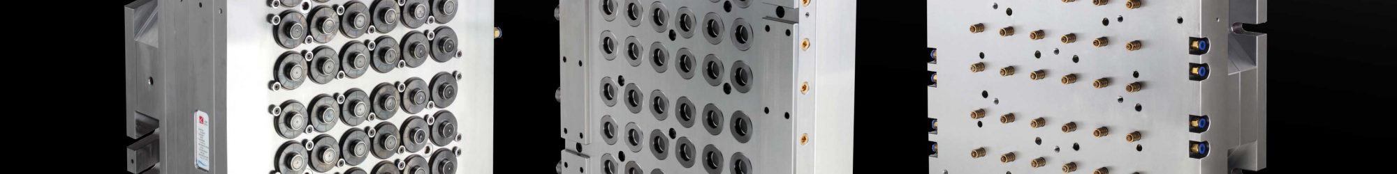
Figure 4 3D diagram of rear mold core
Front mold core is designed with a large insert at battery compartment, and rear mold core is cut with inserts at deep bone position, as shown in Figure 4. Wire cutting is mainly used to process various through-shaped holes and grooves. It is difficult to process materials with high hardness such as hardened steel by conventional machining. For wire cutting, machinability of materials is not limited by hardness, strength and toughness. Easier to process. In order to avoid heat treatment deformation caused by quenching after processing, mold parts must be quenched first and then processed by wire cutting.
Existing wire-cutting machine tools are divided into two types: high-speed wire-cutting (commonly known as fast wire-cutting) and low-speed wire-cutting (slow wire-cutting). Electrode wires of high-speed wire-feeding machine tools are used repeatedly in processing process, mainly including molybdenum wire and tungsten wire. Cmmonly used molybdenum wire specifications are ø0.10mm~ø0.18mm, and ø0.06mm molybdenum wire is also used when cutting smaller arcs or slots. Advantage of tungsten wire is corrosion resistance and high tensile strength; disadvantage is that it is brittle and not resistant to bending, and it is expensive, so it is only used in special cases. Machining accuracy of fast-moving wire is 0.01-0.04mm.
Low-speed wire-cutting machine tools generally use brass wire as electrode wire. Electrode wire runs in one direction at a low speed and is discarded after one use, so high-strength molybdenum wire is unnecessary. Specification of molybdenum wire is ø0.10mm~ø0.30mm. When cutting small arcs or slots, use molybdenum wire with a minimum diameter of ø0.03mm. Processing accuracy of slow wire is 0.002~0.01mm.
Ejection of plastic parts adopts ejector pin and cylinder.
