
Product diagram of front and rear vertical plates of LCD base is shown in Figure 1. Maximum external dimension of front vertical plate is 102.34 mm * 96.70 mm * 73.50 mm, average thickness of plastic part is 2.66 mm, weight of plastic part is 65.64 grams. Maximum size of rear vertical board product is 133.90 mm * 96.60 mm * 71.90 mm, average thickness of plastic part is 2.68 mm, and weight of plastic part is 54.92 grams. Material of plastic parts is ABS, and shrinkage rate is 1.005. Technical requirements of plastic parts are that there should be no defects such as peaks, underfilled injection molding, flow lines, pores, warpage deformation, silver streaks, cold materials, jet lines, etc.

LCD monitor base rear vertical plate
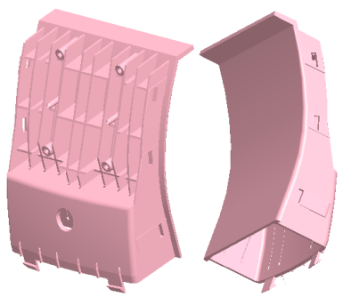
Front panel of LCD base
Figure 1 Product picture of front and rear vertical plates of LCD base
Front and rear vertical plates of base of liquid crystal display are connecting parts of rear shell of display and base. Front and rear vertical boards are combined to form a complete support for display. It can be seen from Figure 1 that structure of assembled plastic parts is an arc-shaped shell, which looks like a gooseneck. Front and rear vertical plates are a set of mutually assembled parts, with suitable sizes and same materials. They are molded in same mold, have same molding conditions, have same shrinkage rate, which can be suitable for mass production and reduce mold costs.
Front and rear vertical boards are connected to each other by 3 sets of buckles on both sides. Because there are 3 buckles on two sides of front vertical plate, a large slider core needs to be designed, the other end has a cylindrical closed space, slider core needs to be designed as well. Two inner sides of rear vertical plate are respectively provided with 3 protruding buckles, which are respectively matched with side holes of front vertical plate. Two arcs on outer side of rear vertical plate also have mold undercuts, and a large slider core needs to be designed.
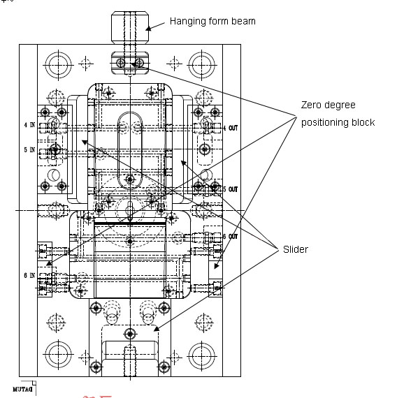
Mold cavity arrangement is 1+1. Since parting surfaces of two cavities are inclined arc-shaped, high part of two plastic parts is in the center of mold, so that lateral force of cavity is roughly balanced. In mold design ranking, two lateral large sliding blocks of rear vertical plate are designed on operating side and non-operating side of mold. Slider of cylindrical enclosed space of front vertical plate is designed on the side of mold. Mold base is CI2545 A110 B90 C80, and zero-degree positioning blocks are designed on three sides of mold to ensure accuracy of mold clamping. Gate of front vertical plate is a concealed gate, and front mold is hidden. In order to prevent gate from being broken in gate sleeve when mold is opened, a dummy gate is designed at corresponding position of back mold, as shown in Figure 6. Gate of rear vertical plate is a horn gate. Both latent gate and horn gate are gates capable of fully automatic injection molding, which can be automatically broken when mold is opened, without manual trimming.
Before mold design, it is necessary to carefully analyze structure of plastic part. In this set of molds, there are many deep bones in front vertical plate, the deepest part is more than 17mm, and there are 6 screw posts in the middle of multiple parallel deep bones, so it is difficult to fill deep bones completely during injection molding. Deep bones are also prone to carbon deposits and damage during electrical discharge machining, processing cycle is long. In addition, mold saving and polishing also have corresponding difficulties. Skill of deep-bone mold design is venting deep in cavity. If correct venting method is not designed, it will be difficult to successfully injection mold. A basic principle of insert design is that bone position is easy to be processed by wire cutting or grinding machine. Some bones are very deep, but bottom of insert is broken or curved, which cannot be completely ground or cut out. You can take the highest point and cut to reduce amount of EDM processing. Strength of mold core matrix should also be considered when cutting inserts, as shown in Figure 5 for insert cutting.
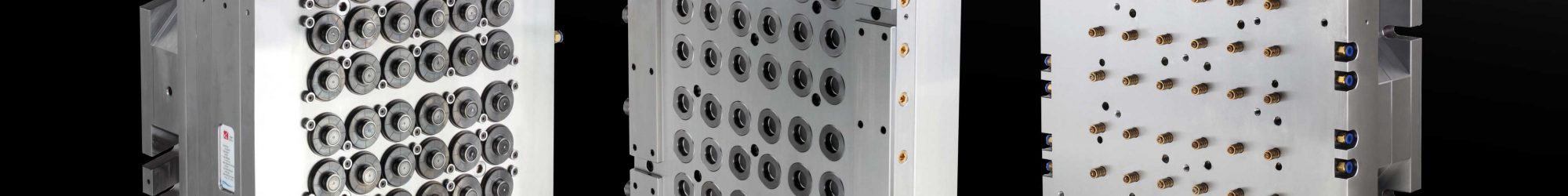
When designing mold, for water transportation, design a 3D water transportation diagram or design a water transportation nameplate to facilitate injection molding personnel to connect to waterway. Water transportation nameplate of this set of molds is shown in Figure 4.
Three sliding blocks are driven by oblique guide pillars, and wear-resistant plates are designed. Ejection of plastic parts adopts thimble, cylinder and inclined ejection. For inclined top, a guide block is designed at the bottom of B plate, and a wear-resistant block is designed on thimble plate. Material and technical requirements of wear plate of slider and wear plate of inclined roof are exactly same.
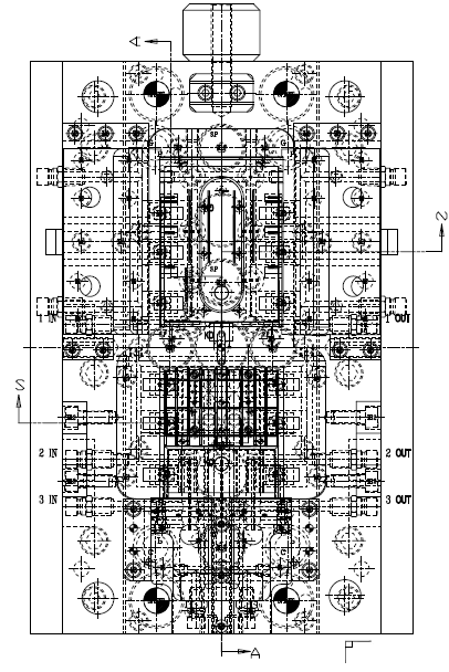


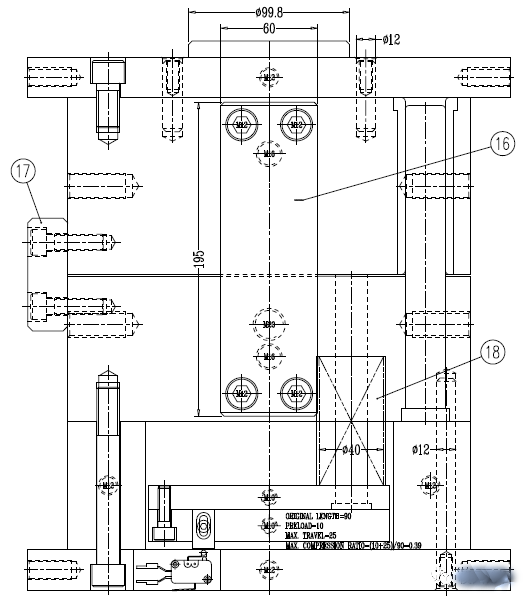
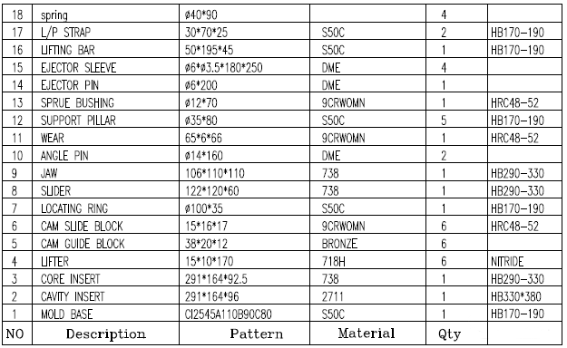
Figure 2 Mould diagram of front and rear vertical plates of LCD base

Figure 3 3D mold diagram
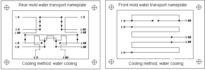
Figure 4 Front and rear model water transportation nameplates
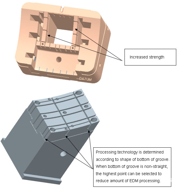
Figure 5 Precautions for insert design
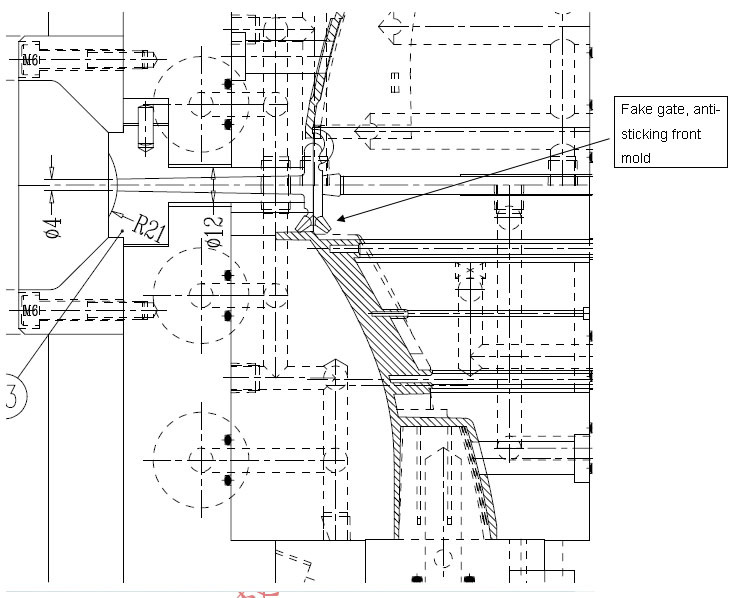
Figure 6 Gate design skills
