
1 Analysis of plastic part structure and molding plan
Medical polypropylene plastic has advantages of high purity, non-toxicity, non-irritation, good chemical stability, no degradation, no inflammation, non-allergic reaction, good biocompatibility, non-carcinogenicity, non-hemolysis and non-coagulation, and can withstand ethylene oxide sterilization treatment. This material not only has good mechanical properties, but also has excellent impact resistance and wear resistance, good dimensional stability and insulation.
Medical infusion bottle cap is shown in Figure 1. It is molded from medical polypropylene. Maximum radial size is φ30.1 mm and height is 18.7 mm. The overall size of plastic part is small but output is large. Combined with actual conditions of mold part processing, mold base and molding equipment, an injection mold with 20 cavities is used for molding. Plastic part molding must be automated in a sterile workshop (no manual contact is allowed). Mold uses point gates to feed materials, and point gate condensate can automatically fall off after mold is opened. When plastic parts are pushed out, no major deformation or push marks can occur, so push rods or push tubes cannot be set up to push out, and forced demoulding is required at ②. Combined with mold layout of 20 cavities, molded plastic parts are pushed out using a push plate. Due to small size at ①, in order to ensure that plastic part remains in movable mold when mold is opened and structure at ① is not damaged or deformed, a two-way push-out mechanism needs to be set up. In summary, mold structure is complex and standard three-plate mold base cannot be used, and a corresponding special mold base needs to be processed.

Figure 1 Medical infusion bottle cap
2 Mold structure design
Although non-standard mold bases are used for molding plastic parts, you can still refer to standard three-plate mold base. In addition, most injection mold parts are standard parts. Therefore, injection mold design mainly includes molding parts design, gating system design, and ejection mechanism design. and cooling system design, design of each part is now explained in detail.
2.1 Design of molded parts
In molding process plan, in order to ensure that plastic part remains in movable mold after mold is opened and that ① (see Figure 1) is not deformed or damaged, fixed mold core 5 must be separated from fixed mold cavity plate 4 first when fixed mold is separated. Since pusher plate is used to push out plastic part, and structure of molded parts adopts mosaic structure shown in Figure 2.

Figure 2 Structure of molded parts
1. Moving mold core 2. Moving mold cavity plate 3. Plastic part 4. Fixed mold cavity plate 5. Fixed mold core
Since plastic part has an asymmetric structure, fixed mold core, cavity plate and movable mold core have directional requirements during installation, and are all equipped with anti-rotation mechanisms. In addition, mold has a 20-cavity structure. After comprehensive consideration, positioning device of fixed mold core, fixed mold cavity plate and movable mold core is shown in Figure 3.

Figure 3 Positioning device of fixed mold core, cavity plate and movable mold core
Positioning means
2.2 Gating system design
In order to realize automatic operation, mold uses a point gate to feed materials, and a pop-up device of gating system is also installed. As shown in Figure 4, after fixed mold is separated, runner condensate is ejected out of mold through pop-up device and falls off automatically. In order to shorten length of sprue and reduce waste, a buried sprue sleeve is used.

Figure 4 Ejection device of the gating system
1. Push plate 2. Ejection device 3. Fixed mold base plate
2.3 Launch institutional design
Mold is pushed out using a pusher plate. In order to ensure that plastic part remains in movable mold when mold is opened and plastic part ① is not damaged or deformed, fixed mold core must be separated from fixed mold cavity plate before movable and fixed molds are separated. Parting surface is opened in a certain order, so a two-way push-out mechanism and a sequential parting mechanism are used.
2.4 Cooling system design
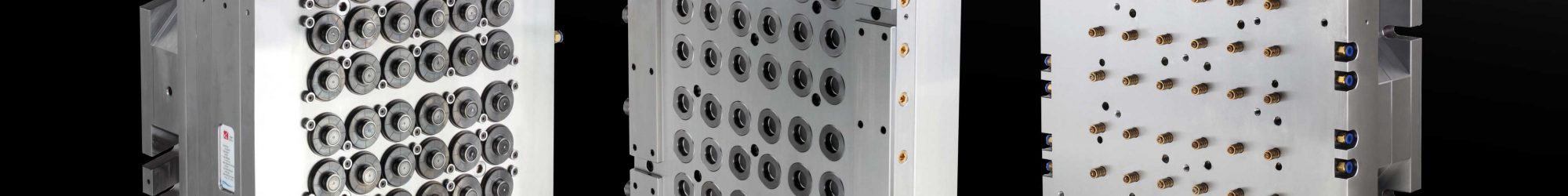
In order to improve production efficiency, shorten molding cycle, and ensure stability of shrinkage rate of plastic parts in each cavity, cooling water channels need to be installed in mold. To facilitate processing and not interfere with other parts, cooling water channels need to be set up in movable and fixed molds respectively. Layout of cooling water channels is shown in Figure 5.

Figure 5 Mold structure
1. Moving mold base plate 2. Push plate 3. Push rod fixed plate 4. Push rod 5. Support plate 6. Extended fixed column 7. Screws 8. Moving model core 9. Round die buckle 10. Moving model cavity Plate 11. Screws 12. Fixed distance pull plate 13. Fixed mold cavity plate 14. Fixed mold core 15. Screws 16. Sheath 17. Fixed mold seat plate 18. Pulling rod 19. Push plate 20. Push plate pad Plate 21. Spring ejection device 22. Sheath 23. Screws 24. Fixed mold fixed plate backing plate 25. Push sleeve 26. Screw 27. Fixed template backing plate 28. Fixed mold fixing plate 29. Spring 30. Fixed template 31. Push Part plate backing plate 32. Push plate 33. Moving template 34. Limiting rod
3. Establishment of analysis model and initial analysis
Since temperature, pressure, time and other factors will cause deformation of plastic parts during molding, molding process parameters must be reasonably adjusted to minimize deformation of plastic parts. If process parameters are adjusted during mold trial, it will not only waste materials, but also extend mold trial time. Moldflow software is now used in combination with orthogonal experiments to obtain optimal process parameters to avoid above problems.
Import plastic part model into Moldflow in STL format, divide plastic part mesh and modify mesh quality, copy plastic part and establish a pouring system, finally establish a cooling system and divide mesh, as shown in Figure 6. Polypropylene plastic with the brand name Escorene PP 9074 is used. According to recommended mold temperature range of 20~80 ℃, cooling water temperature of 25 ℃, recommended melt temperature of 230 ℃, default injection + holding pressure + cooling time, and holding pressure is 80% of maximum filling pressure (66 MPa), initial analysis of cooling, filling, holding pressure, and warpage is carried out. Results of plastic part warpage analysis are shown in Figure 7. The total deformation of plastic part is 0.535 1 mm, and deformation due to shrinkage is 0.470 4 mm, accounting for 87.9% of the total deformation of plastic part, and should be optimized from perspective of uneven shrinkage.

Figure 6 Mold flow analysis model

Figure 7 Warpage deformation of plastic parts
4 Experimental design and result analysis
Based on relevant knowledge and practical experience in injection mold design, Taguchi experimental design method was used to select four factors, including melt temperature, cooling water temperature, holding pressure, and holding time, which have a greater impact on deformation of plastic parts. Each factor took 3 levels (levels of each factor are based on the premise that a geometrically complete plastic part can be obtained ). 3 levels of 4 process parameter factors are selected as shown in Table 1. Test uses total deformation of plastic part S total and shrinkage deformation S of plastic part as indicators, and the smaller values of three indicators, the better. Results after 9 tests are shown in Table 2.
| Factor | 1 | 2 | 3 |
| Melt temperature A/℃ | 230 | 250 | 270 |
| Cooling water temperature B/℃ | 15 | 20 | 25 |
| Holding pressure C/MPa | 54 | 60 | 66 |
| Holding time D/s | 15 | 20 | 25 |
Table 1 Level setting of experimental factors
| Test | A/℃ | B/℃ | C/MPa | D/s | Stotal/mm | Sshrink/mm |
| 1 | 230 | 15 | 54 | 15 | 0.5090 | 0.4273 |
| 2 | 250 | 20 | 60 | 20 | 0.4626 | 0.4088 |
| 3 | 270 | 25 | 66 | 25 | 0.4162 | 0.3803 |
| 4 | 250 | 15 | 60 | 25 | 0.3806 | 0.3308 |
| 5 | 250 | 20 | 66 | 15 | 0.3938 | 0.3446 |
| 6 | 250 | 25 | 54 | 20 | 0.4621 | 0.3818 |
| 7 | 270 | 15 | 66 | 20 | 0.3516 | 0.3043 |
| 8 | 270 | 20 | 54 | 25 | 0.3908 | 0.3212 |
| 9 | 270 | 25 | 60 | 15 | 0.3667 | 0.3001 |
Table 2 Orthogonal test results
Perform range analysis on S total and S shrinkage data in Table 2 (see Tables 3 and 4). It can be seen from Table 3 and Table 4 that melt temperature A has the most significant impact on the total deformation amount S of plastic part and shrinkage variable S shrinkage. Optimal combination of total deformation S of plastic part is A3B1C3D3; optimal combination of shrinkage deformation S of plastic part is A3B3C3D3. Relationship curves between melt temperature and the total deformation amount S of plastic part and shrinkage deformation amount S shrinkage of plastic part are shown in Figures 8 and 9 respectively.
| K1 | 1.3878 | 1.2412 | 1.3619 | 1.2695 |
| K2 | 1.2365 | 1.2472 | 1.2099 | 1.2763 |
| K3 | 1.1091 | 1.2450 | 1.1616 | 1.1876 |
| k1 | 0.4626 | 0.4137 | 0.4540 | 0.4232 |
| k2 | 0.4122 | 0.4157 | 0.4033 | 0.4254 |
| k3 | 0.3697 | 0.4150 | 0.3872 | 0.3956 |
| Extremely bad R | 0.0929 | 0.0020 | 0.0688 | 0.0298 |
| Order of priority | A>C>D>B | |||
| Excellent level | A3 | B3 | C3 | D3 |
| Excellent combination | A3B3C3D3 | |||
Table 3 Range analysis of S total data
| K1 | 1.2164 | 1.0624 | 1.1303 | 1.0720 |
| K2 | 1.0570 | 1.0746 | 1.0397 | 1.0949 |
| K3 | 0.9256 | 1.0622 | 1.0292 | 1.0323 |
| k1 | 0.4055 | 0.3541 | 0.3768 | 0.3573 |
| k2 | 0.3524 | 0.3582 | 0.3468 | 0.3650 |
| k3 | 0.3085 | 0.3541 | 0.3431 | 0.3441 |
| Extremely bad R | 0.0970 | 0.0041 | 0.0337 | 0.0209 |
| Order of priority | A>C>D>B | |||
| Excellent level | A3 | B3 | C3 | D3 |
| Excellent combination | A3B3C3D3 | |||
Table 4 Range analysis of S shrinkage data

Figure 8 Effect of melt temperature on the total deformation S of plastic parts

Figure 9 Effect of melt temperature on shrinkage deformation amount S of plastic parts
Comparing optimal combination of S total and S shrinkage, it is found that only B1 and B3 are different. Combined with Table 2, it can be concluded that the total deformation of plastic part with factor 2 level 3 is smaller than the total deformation of plastic part with factor 2 level 1. Therefore, optimal combination of molding parameters is A3B3C3D3, that is, melt temperature is 270 ℃, cooling water temperature is 25 ℃, holding pressure is 100% of maximum filling pressure, and holding time is 25 s. According to this process condition, warpage analysis was re-carried out on AMI platform. Results are shown in Figures 10 and 11. The total deformation of optimized plastic part is 35% smaller than original one.

Figure 10 Total deformation of plastic parts

Figure 11 Shrinkage deformation of plastic parts
According to requirements and actual production conditions of medical infusion bottle cap plastic parts, injection molding was designed, and Moldfolw software was used to conduct preliminary mold flow analysis of plastic parts to find out main reasons affecting deformation of plastic parts. Through numerical analysis of orthogonal test results, optimal molding process parameter combination with the smallest deformation of plastic part was obtained, which shortened mold trial cycle and reduced production cost. Final molded plastic part is shown in Figure 12, and deformation of plastic part is relatively small. It is small and meets requirements for medical infusion bottle caps, indicating that mold design is reasonable.

Figure 12 Physical medical polypropylene infusion bottle cap
