
Injection molding injection parameters are set in stages. Generally, 4-stage injection and 2~3 stages of pressure holding are the most commonly used and scientific.
268T Garmin machine injection parameter setting page▼

Injection molding machine adjustment includes a lot of content, not just tapping injection molding machine control screen, it includes:
1. Injection molding machine molding parameter setting.
2. Upper mold content, feeding content, and machine inspection content.
3. Check and set safety settings before adjusting machine.
4. Manipulator adjustment and auxiliary equipment adjustment.
5. Unlock mold locking, ejection pin, core pulling, blowing and other demoulding parameters, and set mode.
6. Molding auxiliary action needle valve delay device, hot runner parameter setting.
7. Adjust shaping fixture and shear nozzle fixture.
8. Setting parameters such as injection base, melt glue, and barrel temperature of injection molding machine.
9. Clean mold before adjusting machine, perform maintenance actions, perform maintenance during production, handle minor abnormalities in mold and equipment.
10. Instruct and supervise operating movements of machine side operators.
Above ten items are collectively called injection molding workshop adjustment content. Now we will use a 268-ton domestic Jiaming machine and a set of 1-8 molds to explain the first item: setting molding parameters of injection molding machine.

First of all, estimate amount of glue used for PC material in the picture above, 1 out of 8, three-plate mold, needle point into water, glue level thickness 1.2mm? Preset melting stroke is 100mm. According to characteristics of PC material used in our factory, set melting temperature and set glue extraction stroke to 6mm based on experience. .
268T Garmin gun barrel parameter setting page▼

The first section, water entry section of nozzle stroke, depends on material used for nozzle of product, and water is entered at a needle point. Use 120 pressure, 55 speed, shoot from 106mm to 85mm. This section is journey where water outlet and forward glue enter product just past needle point where water enters. For PC materials, water outlet stroke requires higher pressure and medium speed is better.
We should pay attention: injection speed of the first section is determined by water entry form of product and shape of product. If water is directly entered from side of product or square shape, speed of glue passing through water entry position is extremely slow, generally 1 to 20. Especially production of PC material lenses! If it is too slow to walk, you can share the first and second sections as water outlet travel section, that is, the first section is faster, about 10 to 20, and second section is very slow, about 1 to 10. Positions of two sections should be set scientifically and reasonably.
In second section, rapid glue injection section, forward glue has passed through water level. According to shape of product, it needs to quickly reach 95% to 99% of glue amount of product. Use a pressure of 138 and a speed of 75 to go from 85mm to 36mm to complete basic shape of product and amount of glue.
Friends, please note that setting of this section should be set according to shape of product. Some products have puncture points, uneven thickness, or serious corners. It is necessary to set up an extra section and move slowly through puncture points. At the same time, exhaust problem should also be considered, and speed of this fast section should be set according to actual condition of mold.
The third section, buffer exhaust section, has a pressure of 80 and a speed of 26, slowly going from 36mm to 33mm. Slow down, let gas escape, and slowly fill glue.
Burnt, yellowed, and tail joint lines of product are adjusted during this period! Friends, don’t forget, you made a mistake.
In the fourth section, feeding transitions to pressure-holding section. With a pressure of 30 and a speed of 10, filling is started from 33mm downward until 2.8-second injection time is completed, and then enters pressure-holding section.
Guys, rubber injection tail section is pressure-maintaining and feeding section. If some simple products do not require pressure-holding, feeding and pressure-holding section is replaced by rubber injection tail section.
V→P mode (pressure holding mode) of this explanation is a time mode. Screw must complete injection time before entering pressure holding period (position mode is that screw enters pressure holding section when it reaches VP position).
As for injection pressure, some machines, especially imported machines, only use one stage of injection pressure. Unlike domestic hydraulic machines, injection pressure can be adjusted in multiple stages. Everyone needs to understand meaning of this.
In pressure-holding section, after injection screw moves forward for 2.8 seconds to inject glue, it enters pressure-holding section, feeds forward for 1 second at a pressure of 48 and a speed of 10.
In the first stage of holding pressure, in order to prevent burrs from emerging, pressure is generally set smaller to allow outer glue of product to cool down, then holding pressure is increased for shrinkage and filling.
In the second stage of pressure holding, after the first stage of low pressure holding, slowly cool down outer glue level, continue filling and feeding forward at a high pressure of 85 and a speed of 12 for 2 seconds. Length of pressure holding time is based on cold sealing of water inlet to obtain a product that does not shrink and has acceptable dimensions.
Under normal circumstances, in order to prevent screw from rebounding violently after pressure holding is completed, a low-pressure and low-speed 0.5-second holding section will be set at the end of pressure holding as a buffer.
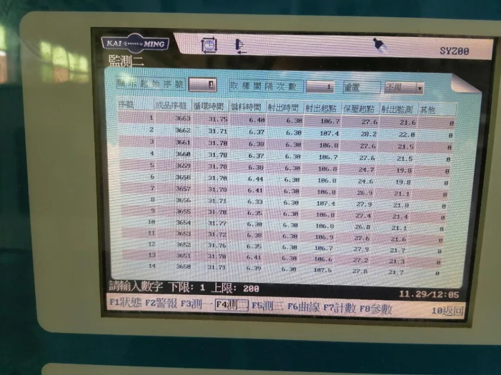
268T Garmin machine statistical parameter observation page▼
Friends, above is the most commonly used segmentation idea for machine adjustment. If you carefully understand it, you can solve adjustment of most product molding parameters in injection molding.
Finally, go to quality control office to sign the first piece and teach operators to start production.
Now that machine is on, it’s important to continue to improve your movements!
1. After 2 hours of normal production of the first piece, go back and improve to shorten cycle by 2 to 3 seconds; after half a shift of normal production, go back and improve to shorten cycle by 2 to 3 seconds, continue to achieve efficiency and quality Best state.
2. Shorten cycle and improve production efficiency! (Consider cooling conditions, mold opening and closing speed, position, manipulator movement, mold, etc.).
3. Injection molding cycle, except for injection and holding pressure time, is all useless time! To reduce as much as possible.
4. 80% of causes of defects in injection molded products are mold problems, and 70% of mold problems are caused by design. Problems found by injection molding technicians during production must be reported in writing to mold engineering, project engineering, and mold repair master when making final piece, such as: poor cooling effect, water entry form, location, exhaust location, size, demoulding form ——
5. Optimize product appearance: shrinkage, air lines, thread clipping, rough edges, yin and yang colors, shine, etc. to improve customer experience.
